Loading Shovel Pin & Bush Identification Sheet — Volvo Construction & UK Loading Shovels
A loading shovel — also called a wheel loader, payloader or shovel loader — uses a parallel-linkage boom and a Z-bar or T-P (tool-pivot) linkage to drive the bucket. Each linkage has multiple pins and bushes that wear over time. This guide gives you a numbered identification sheet you can use during inspection or when ordering replacement pins, bushes, bucket teeth and adapters.
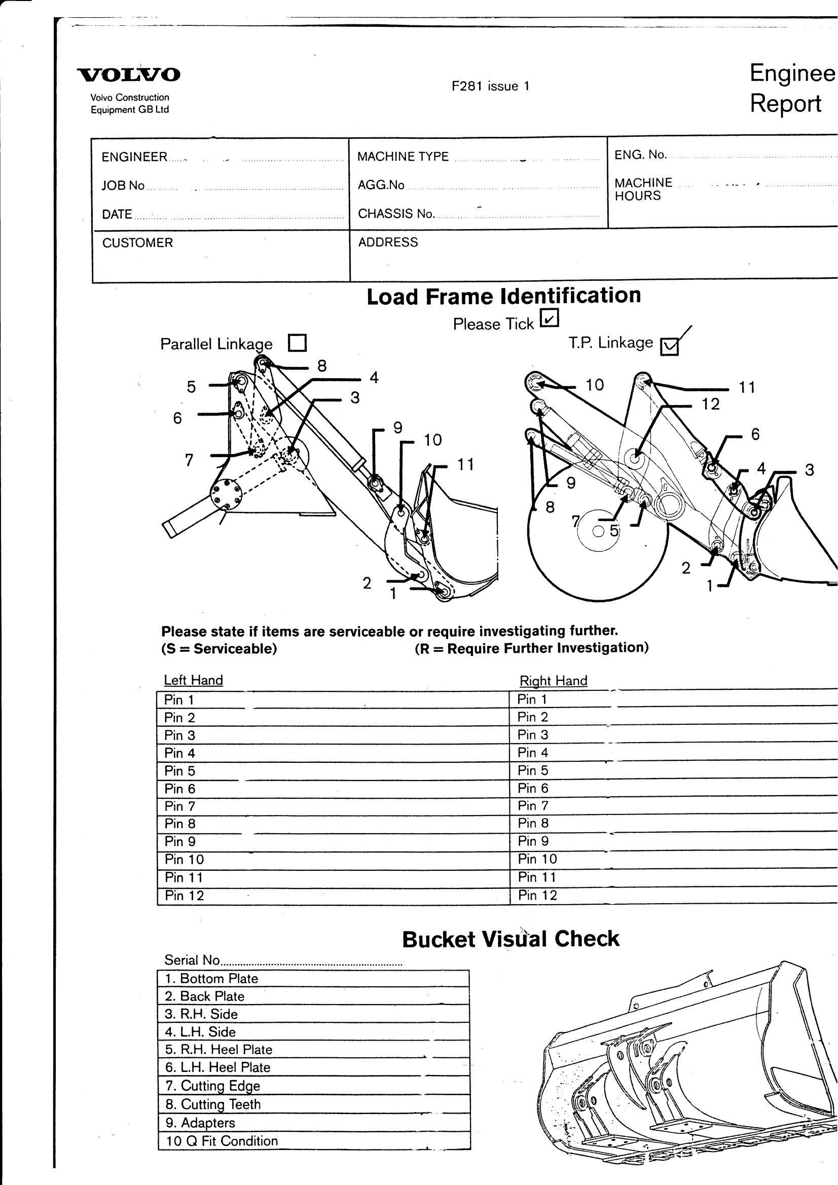
Loading Shovel Pin Identification Sheet
The form below — based on the Volvo Construction Equipment GB Engineer Report F281 — covers a typical loading-shovel load frame and bucket arrangement. It records up to 12 pin positions, plus the bucket bottom plate, back plate, side plates, heel plates, cutting edge, cutting teeth, adapters and Q-fit hitch condition.
How to use this sheet
For each pin position 1–12, mark whether the joint is:
- S — Serviceable (no excessive play, no wear ridge, grease retained)
- R — Requires further investigation (visible play, oval bore, lost grease, scoring)
Record findings separately for the left-hand and right-hand sides of the linkage — wheel loaders often wear unevenly because the operator favours one side for spoil dumping.
Bucket and ground engaging tools (GET) checks
Below the pin section, the sheet covers the bucket components and ground engaging tools. Always inspect:
| Item | What to look for |
|---|---|
| 1. Bottom plate | Wear-through, repair plate condition, fixings tight |
| 2. Back plate | Fatigue cracking around bucket pivot, weld condition |
| 3. R.H. side | Erosion of the cheek, loose fixings, plate flatness |
| 4. L.H. side | As R.H., plus check for impact damage on the leading edge |
| 5. R.H. heel plate | Wear remaining vs original thickness |
| 6. L.H. heel plate | As R.H. — heel plates protect the bucket on hard floors |
| 7. Cutting edge | Bolt-on edge bolt torque, wear pattern (uniform vs hooked) |
| 8. Cutting teeth | Tooth length remaining, locking pin condition |
| 9. Adapters (tooth bases) | Crack inspection, weld integrity |
| 10. Q-fit hitch condition | Pin engagement, locking lever travel, retention bolts |
Common loading shovel pin & bush problems
- Boom-pivot pin ovality from heavy-side loading during pile-loading work.
- Tilt-link bush wear is the first joint to show play because it sees the highest cycle count.
- Pin retention bolts shearing if greasing is missed and the bush seizes to the pin, which then rotates inside its retainer.
- Bucket-cylinder pin wear when the operator regularly crowds the bucket against the stops to break out spoil.
A worn pin/bush set on a wheel loader shows up as bucket "slop" at full crowd, an audible knock on direction reversal, and visible play with the bucket lifted clear of the ground.
Compatible machines
This identification sheet covers the loading-shovel/wheel-loader linkage geometry common to:
- Volvo Construction Equipment — L60–L350 wheel loaders
- Caterpillar — 9xx, 95x, 96x, 98x and 99x wheel loaders
- JCB — 411–467 wheel loading shovels
- Komatsu — WA series wheel loaders
- Hitachi Construction Machinery — ZW wheel loaders
- Doosan — DL wheel loaders
- Liebherr — L wheel loaders
- Manitou — MLA articulated loaders
For the equivalent reference covering excavator boom and bucket pin positions, see our Excavator Pin & Bush Diagram.
Need help identifying or sourcing loading shovel pins and bushes?
Send us a photo of the joint plus your machine make, model and serial number, or fill out the inspection sheet above and email it across. We supply genuine and quality aftermarket pins, bushes, bucket teeth and adapters with same-day dispatch on stock items.
Contact us for a quote, or call 01255 323202 to speak to one of our parts team.